THE HEARING REVIEW: Volume 2, Number 10; NOV / DEC, 1995 pp 12 - 16
VIDEO OTOSCOPY: Basic and Advanced Systems
By Roy F. Sullivan, Ph.D

A thorough otoscopic examination has always been an essential first step in prevalidating the audiometric assessment of hearing and the selection and fitting of custom hearing instruments. A learned clinical skill, otoscopy requires adequate visual acuity, perceptual learning, technical aptitude, an awareness of the range of normal anatomical variations and a familiarity with those conditions of the pinna, concha, external auditory (EAC) canal and middle ear,- as viewed at the tympanic membrane (TM) - which may require medical referral, special consideration in hearing instrument fitting or both.
Video Otoscopy (VO) provides an opto-electronically enhanced field of view of the ear which can be shared with the patient. VO images can be enlarged and focussed in a way not possible with standard otoscopy. They may be stored on disk or tape, recalled and reproduced via Polaroid photoprint or computer ink-jet printer and transmitted by modem.
In the five years since its introduction to hearing health professionals , Video Otoscopy has become an invaluable clinical tool with more than one thousand systems used in hearing health practices.Today,VO instrumentation is available in both clinical and portable models from a number of manufacturers including Grason-Stadler (Welch-Allyn); MedRx, Siemens and Starkey (JedMed). Siemens also distributes VO equipment through Rexton. MedRx supplies VO units for Argosy, Beltone, Electone, Finetone, Hal-Hen, HSI, Lori Labs, Magnatone, Maico, Miracle Ear, Micro-Tech and Qualitone.
VIDEO OTOSCOPY SYSTEM
Figure 1 presents the components of a Video Otoscopy (VO) system in block diagram format. For discussion purposes, these components may be divided into Analog or video-based (pink/blue) and Digital or computer-based (green) categories. Given the rapid advance of video and computer technology, the analog/digital dichotomy can be anticipated to merge into a single (digital) category. Yellow blocks represent optional features. Dashed lines represent optional / alternative component inter-connections.
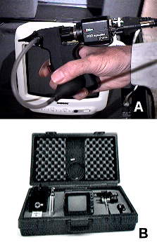
Fig. 1.Basic, portable composite video VO systems from (A) Starkey and (B) Rexton.
For audiological applications, video otoscopy may be divided into two categories: Video Oto-Endoscopy (VOE) and Video Oto-Macroscopy (VOM).
In VOE, an endo[scopic]-otoscope or rod otoscope with a concentric fiber optical light source is used to examine the external auditory canal and the tympanic membrane. In VOM, a macro- or close-up (CU) lens is used in place of the rod otoscope to facilitate videography of a hearing aid in situ, the concha, pinna and peri-auricular areas.
VO SYSTEM: ANALOG COMPONENTS
The video / analog components described in he following paragraphs are fundamental to the implementation of a video otoscopy system in a hearing health practice. These systems may be categorized as Basic; (i.e. on-line video otoscopy only) and Enhanced VO with options for freeze-frame, multiple hard copy image reproductions, image formatting and oto-macroscopy.
BASIC VO SYSTEM
The basic VO system (Fig. 1, pink blocks) consists of a rod otoscope with removable otic speculum, color video camera, high intensity light source and a video display monitor. Fig. 2 presents two portable composite video systems containing each of these components. One (B) allows the rod otoscope to be alternatively mounted on a standard otoscope handle for ocular viewing. The other (A) features a light source which is integrated within the "pistol grip" handle and activated when the "trigger" is pulled. Basic portable systems generally function on-line only and cannot freeze-frame or store VO images. A very optional portable videotape recorder can serve as a less-than-optimal medium for storing VO records.

Fig. 2. Block diagram of a comprehensive analog / digital Video Otoscopy system. Components are color-coded: analog basic (portable): pink; analog enhanced: pink + blue; digital: green; analog or digital system options: yellow blocks represent optional / alternative compnent interconnections.
Fig. 3 presents four enhanced VO systems, designed for clinical, fixed site application, distributed by Starkey (A), Siemens (B), Grason-Stadler (C) and MedRx (D). Enhanced features typically include a higher resolution S-video camera (C), amplifier (A), monitor (M), a variable, high intensity light source (L) and an image format / video printer (V).

Fig. 3. Enhanced clinical VO systems from (A) Starkey; (B) Siemens; (C) Grason Stadler and (D) MedRx. Components include (C) otoscope / camera ; (A) amplifier; (M) video monitor; (L) light source; (V) image format / video printer with (R) remote control.
VIDEO OTO-ENDOSCOPE (VOE)
Fig. 4 shows an oto-endoscope or rod otoscope designed for ocular, rather than video, viewing at a fixed focal length.

Fig. 4. Fixed focus rod otoscope designed for ocular viewing. (A) endoscopic rod; (B) twist lock otic speculum; (C) ocular eyepiece; (D) fiber optic light bundle.
The stainless steel rod casing (Fig. 5) is typically 30 - 40 mm long containing a central solid rod lens which transmits the otic image and a circumferential fiber optic bundle which transmits the source light. The narrow diameter of the rigid rod, less than 3mm, facilitates an intimate examination of the TM and EAC. This differs from flexible medical endoscopes in which both image and source light are transmitted via concentric flexible fiber optic bundles.

Fig. 5. Schematic diagram of the oto-endoscopic rod.
Otoscopic fields of view may vary, among manufacturers, from 10 degrees for some standard non-video otoscopes through 80 degrees for commercially available VO systems. With otic speculum in place, the tip diameter ranges from 4.0 - 5.0 mm, facilitating a full screen, circumferential image of the tympanic membrane. Fig. 6 shows a comparison of luminance levels, image size and spherical aberration among three different model VOE heads using the same light source and distance from the 1 mm calibration rulings.

Fig. 6. Variability (A-C) in luminance levels, image size and spherical aberration among three different video rod endoscopes.
Fig. 7 identifies the features of a representative clinical video oto-endoscope. The endoscopic rod (A) is reinforced (B) to facilitate use of a disposable cerumen wax loop (D) as well as the autoclavable otic speculum (C). The Siegle bulb (E) is particularly important for visual verification of TM mobility, differentiating monomeric scars from perforations and for clearing condensations from the distal rod lens. The change from room (~68oF) to body (98.6oF) temperature at higher humidity levels often causes the VO lens to fog. Application of the bulb quickly restores a clear field of view. The fine focus (F) can be changed easily while the VO head is in situ. A quick release ring (G) permits rapid interchange between the standard VOE and the VOM lens systems.

Fig. 7. Enhanced video otoscope: (A, B, I) Video oto-endoscopy (VOE) head; (A) endoscopic rod; (B) rod brace for cerumen curettage; (C) autoclavable otic speculum; (D) disposable cerumen loop; (E) Politzer bulb; (F) in situ focus knob; (G) quick release for video oto-macroscopy (VOM) lens; (H) 1/2" 2.5 lux S-video camera; (I) fiber optics source light cable; (J) camera cable.
VIDEO OTO-MACROSCOPE (VOM)
Because of its specialized optical design, the VOE head is poorly suited to macro-videography of the pinna and concha with hearing aids in situ. The VOM macro-lens accessory is an optional feature but particularly helpful in a hearing instrument - based practice. It affords the opportunity for a broad field of view at ambient light levels. It is useful for capturing images of the entire pinna and concha, for documenting needed changes in hearing instrument morphology to the laboratory and for demonstrating hearing aid placement, adjustment and cosmetic impact to the patient. In some cases, a second camera and lens can be dedicated to VOM applications as well as patient "mug shots" for clinical records.
Fig. 8A shows a contact ulceration of the medial antitragus caused by pressure from the sharp edge of a canal aid battery compartment. The edge was ground away relieving the irritation but also (FIG 8B) creating a hiatus into which the aid subsequently extruded. This, in turn caused slit leak with acoustic feedback. Using a VOM image, an outline of an antitragal lip (ATL) was drawn (Fig. 8B) and forwarded to the laboratory. The resulting ATL (Fig.8C) distributed pressure evenly across the entire medial antitragus, eliminated the contact abrasion and prevented both extrusion and feedback.

Fig. 8. Video oto-macroscopy (VOM) application: (A) ulceration of medial antitragus induced by contact with canal aid faceplate / battery compartment. (B) Result after grinding back contact areas, pressure improved but aid extrudes causing slit leak / feedback. Dashed line provided as a VO photo reference for laboratory shell technician to fabricate antitragal lip (ATL). (C) ATL stabilizing aid, spreading pressure and eliminating extrusion-based feedback.
The right and left pinnae / conchae of the patient shown in Fig. 9 A and B demonstrate clearly disparate anatomical configurations. The left ear was flattened in a forceps-delivery birth. In a binaural canal aid fitting, the right aid was cosmetically acceptable, the left aid protruded significantly because of the iatrogenically shallow inferior portion of the concha. A VOM image (Fig. 9C), highlighting the area of cosmetic unacceptability, was forwarded to the laboratory together with the hearing aid investment. The outcome is shown in 9D.

Fig. 9. VOM application: (A) right and (B) left pinnae / conchae of the same adult female patient. Left pinna / concha is shallow, attibutable to birth trauma. (C) Cosmetically unacceptable canal aid protrusion indicated on VO photo for shell technician. (D) Recontoured faceplate.
REMOTE LIGHT SOURCE / FIBER OPTIC CABLE
While miniature color video cameras are capable of functioning in relatively low light levels (2.5 - 5 lux), the long, narrow aperture of the VO rod endoscope restricts both source and reflected otoscopic image light. Consequently, there is a need for a relatively high intensity light which does not generate heat at the viewing point. The source light for most VO systems is produced by a remote, fan-cooled quartz halogen bulb, of the type found in 35 mm slide projectors or by a metal halide / arc type lamp (Grason-Stadler). The latter light source produces an illumination spectrum more like daylight (color temperature ~5500o Kelvin) while the former spectrum (color temperature ~3400o K.) is consistent with indoor tungsten photographic lighting. If a video camera is adjusted for other than the correct source light color temperature, the video otoscope image will appear chromatically biased toward the red or blue ends of the visible light spectrum, respectively.
Fortunately, all quality VO camera systems have a white balance feature which allows the user to color-correct the image, regardless of the type of source light. Most VO light sources contain a control to vary the illumination level. The light is then transmitted via a flexible fiber optic cable to the VO head, essentially without heat.
COLOR VIDEO CAMERA / CAMERA AMPLIFIER
Video otoscopy substitutes a miniature color video camera (Fig. 3A-D / C) for the eye at the focal point of the rod (VOE) or macro- (VOM) lens. The television signal produced by the VO camera contains a luminance component (Y) with luminous intensity information, perceived as brightness, and a chrominance (C) component that transmits the two color parameters, hue and saturation, perceived as color and purity, respectively. Two different video signal formats are used in VO, composite and S-Video component. In the composite format, the luminance (Y) and chrominance (C) components are combined and transmitted in a single channel. The S-video component format separates and transmits (Y) and (C) on separate channels. Typically, an S-VIDEO component system has a wider bandwidth which produces a higher horizontal resolution of vertical lines and superior color definition to that obtained with a composite video system.
Both composite and S-Video component formats in the United States, Canada, Mexico and Japan conform to the NTSC (National Television System Committee) standard for TV signal generation used in the U.S. TV broadcasting industry. This standard specifies a screen image or frame consisting of 525 horizontal (raster) scan lines refreshed at ~60 image halves per second, ~1/30 second each for the odd and even scan lines. Of the 525 lines, 440 are active in the viewed image. VO systems used in other countries are manufactured to conform to the indigenous TV industry standards, typically PAL (Great Britain, Germany, Austria, Italy and Scandinavia) and SECAM (France, Soviet Countries).
The heart of the video camera is a tiny CCD (charge-coupled device) chip which converts optical images to video signals. More than 400,000 light sensitive picture elements or pixels are integrated on a 6.5 X 5 mm surface. Complementary color filters are placed on top of each pixel so that a color analysis of the subject can be made and the fundamental additive color signals of red, blue and green (RGB) can be interpreted by the color demodulation circuit.
The camera amplifier / power supply (Fig. 3 A-D / A) contains variable controls for automatic, semi-automatic and manual white balance, automatic (light sensitivity) gain control and electronic shutter speed.
VIDEO MONITOR
The video camera, video display monitor (Fig. 3 A-D / M ) and video printer all must conform to the same composite or S-Video signal format. Some VO systems use home video monitors / TV sets, available in both composite and S-Video formats. However, the additional investment in a professional video monitor is generally warranted by the superior image resolution and color quality obtained in both signal formats. For VO in most professional office clinical settings, a 13" diagonal screen provides an adequately sized view for both clinician and patient. In an advanced level computer-based system, the VO image may be monitored virtually on-line using the computer monitor. At present, it is more convenient to use separate monitors for on-line VO display and for off-line image capture and processing.
IMAGE FORMAT / VIDEO PRINTER
The image format / video printer (Fig. 3 A-D / V ) greatly enhances the capabilities of the basic VO system. It adds the following capabilities to the basic VO system:
Fig.10B shows a Polaroid VO photograph which has been formatted to display two images each of the right and left tympanic membranes in a single exposure. The author has created a print-sized 4" by 5.75" computer-generated cover label containing information about the image (Fig. 10A), which is stapled over the face of the photoprint for transmission to the primary care and/or ENT physician.

Fig. 10. (A) Polaroid process VO photoprint showing four image print format; bilateral large, dry central perforations; upper images / right ear; lower images / left ear. (B) Photo-size transmittal form containing information about the image(s) for the physician.
VO SYSTEM: DIGITAL COMPONENTS
In order to store, edit, recall, compare and print VO images as patient records, it is necessary to provide an interface from the VO analog system to a computer which has been adapted for this purpose.The author's office VO system, containing a full range of analog and digital features, is shown in Fig. 11. Because of the author's clinical text and hypertext publishing requirements, this system transcends the requirements for routine application in a hearing health practice. The digital extension of a VO system is invaluable in a practice where VO is used routinely in patient hearing aid and hearing health follow-up. To date, two companies, Starkey and Lori Labs, provide integrated hardware, software and technical support for computer-based Video Otoscopy in a hearing health practice.
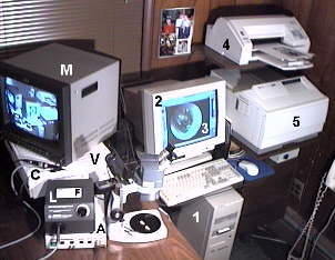
Fig. 11. The author's analog / digital research-level VO system. (C) VOE head with S-video camera; (not shown) dedicated VOM camera; (A) VOE camera amplifier / power supply; (M) professional 13" video monitor; (V) image format / professional level video polaroid printer; (L) 150 watt halogen light source; (F) focus / orientation card w/ 1mm vertical rulings; (1) Pentium 90 CPU with 16 mbytes RAM, 2 X 1.25 gByte hard disk drives; qic-80 hard-disk-backup drive; [ 980 mB CD-ROM recorder/reader ], 28.8k baud FAX / modem; (2) 17" high bandwidth SVGA monitor; (3) image processing and cataloging software; (4) 720 X 720 dpi color inkjet printer; (5) 600 X 600 dpi, 16 ppm black and white laser printer.
COMPUTER: Because of the raw processing power required to capture and store clinical quality VO images, a minimum 486 / 50mhz central processing unit (CPU) with 8 Mbytes RAM is necessary. If a new computer is being purchased, a Pentium 90mhz processor with 16 Mbytes RAM is desirable to allow for Windows 95 or other RAM-intensive 32 bit operating systems.
VIDEO CAPTURE BOARD: This special purpose add-in board allows direct input of composite or S-Video component signals to the computer. Some video capture boards incorporate graphic accelerator and display driver functions. Others are independent of the video graphics board which drives the computer monitor. These devices range from inexpensive, parallel port external units through costly, broadcast-quality internal PCI cards. The analog video signal is converted to digital bitmap which can be frozen, captured, edited and stored as a file in a variety of computer graphic formats.
The most efficient storage format is .jp[e]g (journalists picture [expert] group) which can compress a 900 kbyte, full frame 640 X 480 pixel bit mapped VO S-video image into a 15 - 25 kbyte .jpg file with no significant loss of resolution. For clinical purposes, NTSC video images can be captured in a 1/2 frame format of 320 X 240 pixels. The resulting file size in bit-mapped (*.dib or *.bmp) format will be on the order of 225kBytes. When saved in *.jpg file format at a compression factor of 50, a pair of right and left ear images can be stored in as little as 12k bytes of hard disk space. This extrapolates to more than 80 patient right/left ear VO records per megabyte.
HARD DISK: For routine clinical purposes, a minimum hard disk capacity of 512 mbytes is suggested for half-frame images stored in *.jpg compressed format. A 1 gigabyte drive is recommended if full frame images are stored in a non-compressed file format. Allowance should be made for the larger storage requirements of new operating systems, programs and a clinical record database.
COMPUTER MONITOR: A 15 inch Super VGA (SVGA) monitor is the minimum size recommended for digital applications. However, the VO image size on a 17" SVGA monitor closely approximates that of a 13" analog S-video monitor. The combination of video graphics accelerator board and SVGA monitor should be capable of displaying an 800 X 600 pixel image at a 24 bit color depth; i.e. 16 million colors or "true color" and a 1024 X 768 pixel image at a 16 bit color depth; i.e. 64000 colors or "high color". Because of an 8-bit color limitation, laptop computers with LCD displays and VGA monitors cannot be used for video otoscopy.
SOFTWARE: The clinician has a choice of using software dedicated to VO application in a hearing health practice or using generic programs. At this time, only Starkey and Lori Labs have dedicated VO software packages. The Starkey Pro-HEAR STARBASE software is a NOAH-compatible platform for integrating Video otoscopy images with patient records including audiometry, tympanometry, hearing aid fitting and patient anecdotal data. Complete patient files may be recalled, displayed, printed and combined into computer-printed text reports to physicians. The Lori Labs program also incorporates audiometric and patient record data.
For VO-specific applications, video capture boards are typically bundled with image editing software which can be adapted for VO image capture, editing, storage, recall and printing. Fig. 12 shows how editing software can be used to enhance a VO image. An external auditory canal hair is seen (A) highlighted by the fiber-optic light. With image-editing software, the artifact can be removed easily (B). Software is available for cataloging an entire VO image library in convenient "thumbnail" representations.

Fig. 12. Application of VO image-editing software. (A) EAC hair artifact distorts image; (B) Digitally retouched VO image.
COMPUTER COLOR PRINTER: Video capture and specialized VO software permits printed image output to a color computer printer. At present, an ink-jet printer capable of 600 X 600 dpi (dot per inch) resolution is necessary for clinical quality VO reproduction. Unfortunately, color printing at this image resolution is time consuming, measured in minutes per page (mpp) rather than pages per minute (ppm). A desirable feature of the video capture board is an analog video output which can be directed back to the Polaroid video printer, producing a videoprint in less than one minute. The author's computer-generated VO report form for physicians is shown in Figure 13.

Fig. 13. Computer-generated VO report for the physician produced on the ink jet color printer.
IMAGE ARCHIVING: If the number of full-sized VO images and records becomes substantial, it is worthwhile to consider optional, alternative long-term storage / archival media to the computer hard disk. These include qic-80 format hard-disk-backup tape backup drives; "zip"-type removable floppy disks and floptical (writeable optical) disks. A twenty dollar 100 -135 mbyte "zip-type" [reuseable] disk can easily store a full year of VO records for a moderately busy practice. [For large .bmp format VO image databases, CD-ROM disk writer/readers are available for under $1000 with WORM {Write Once Read Many} media available at $10-15 per disk.]
MODEM: While not an integral component of the VO system. A high speed; i.e. 14.4k - 28.8k baud modem can be used to transmit VO data as E-Mail attachments to the offices of physicians and colleagues who are similarly equipped. The modem also facilitates contact with VO hardware and software manufacturers for technical support by E-mail and by the Internet World Wide Web.
WWW VO FORUM: In addition to VO seminars presented at AAA conventions7,8, the author has made available an evolving Internet World Wide Web site dedicated to sharing information on video otoscopy with the audiological community and other colleagues in the hearing health professions. Graphical web browsers functioning at HTML level 2.0 or 3.0 may be directed to:
E-Mail inquiries about Video otoscopy may be sent to the author care of:
1. Sullivan, R.: How video otoscopy benefits hearing health practice. Hearing Instruments, 44, 4, 1993, pp15-17.
2. Sullivan, R.: Audiologic applications of video otoscopy. Hearing Journal, 48, 8, 1995, pp 10, 41-48.
3. Hawke, M.: Clinical Pocket Guide to Ear Disease. Lea and Febiger, Philadelphia, 1987. [out of print]
4. Hawke, M., Keene, M. and Alberti, P.:Clinical Otoscopy, An introduction to ear diseases. Churchill, Livingstone, Edinburgh, 1990.
5. Hawke, M.: Otitis Media: A pocket guide. Smith, Kline Beecham; Decker Periodicals, Toronto, 1994.
6. Hawke, M. and McCombe, A.: Diseases of the Ear: a pocket atlas. Starkey; Manticore Communications, 1995.
7. Hawke, M. and Sullivan, R.: Video Otoscopy; Presentations at 1994, 1995 AAA conventions. Co-Sponsored by Starkey Laboratories.
8. Sullivan, R.: Video Otoscopy in Audiological Practice; Presentation submitted for the 1996 AAA convention.